OSENC Magnetic Separation
Position, Height and Commissioning
Install a suspended magnet from the approved project drawing: confirm inline or crossbelt position, measure suspension height from the specified datum, verify the support structure and lifting points, remove harmful steel interference, provide a safe iron-discharge path, and test at real burden conditions. Do not set the height from belt width or a catalogue image alone.
Request Project Installation Documents Review Suspended Magnet Selection
Before Installation
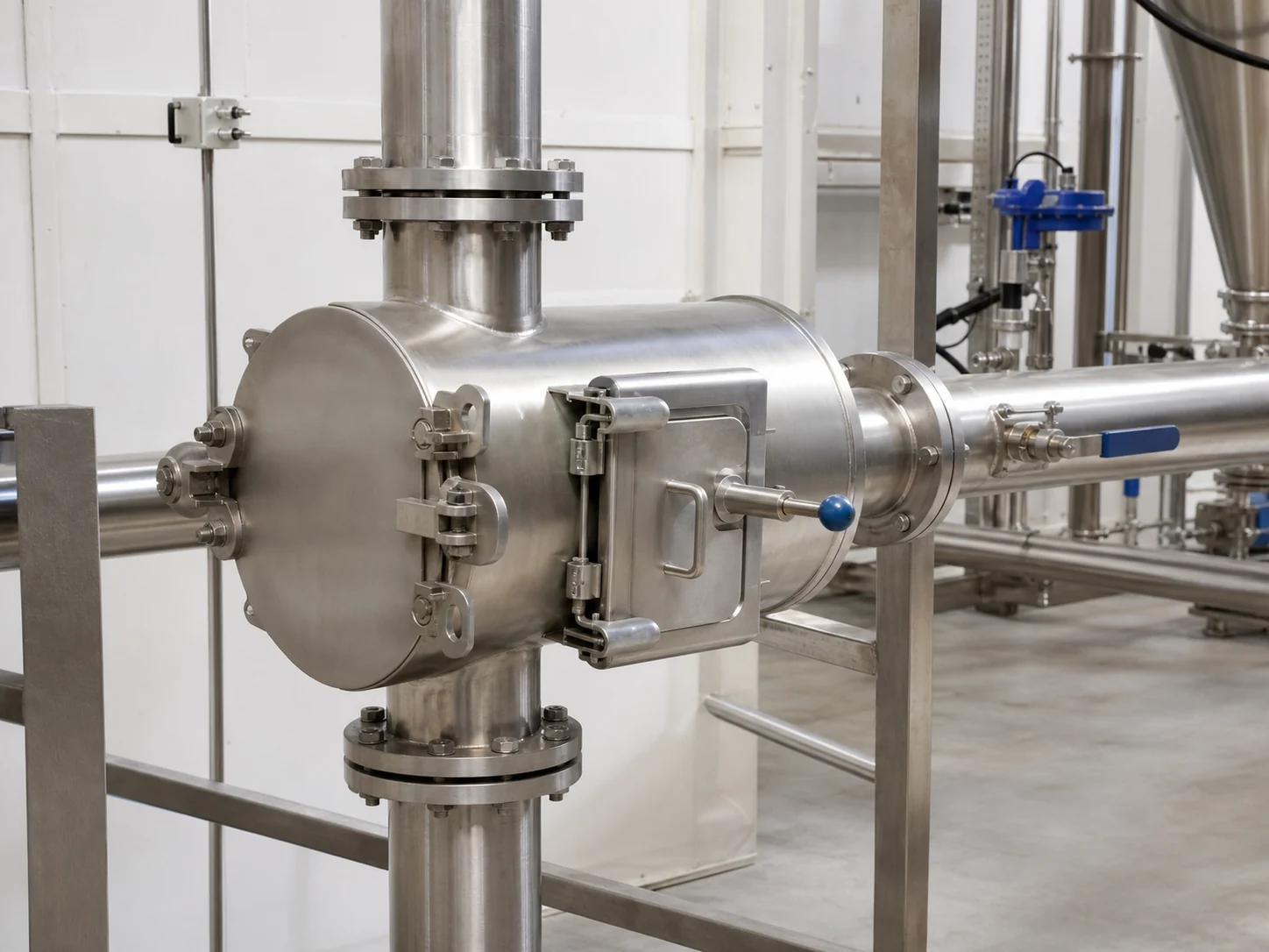
- Confirm equipment model, total mass, center of gravity, lifting points, and shipping restraints.
- Approve support loads, dynamic effects, attachment points, and corrosion environment with the responsible structural engineer.
- Verify belt width, trough, speed, normal and peak burden, material trajectory, and target iron.
- Define the height datum on the drawing—for example belt surface, material surface, or magnet face reference.
- Confirm access for cleaning, inspection, lifting, and removal.
Inline or Crossbelt Position
| Arrangement | Potential advantage | Installation question |
|---|---|---|
| Crossbelt | Side discharge and flexible conveyor position | Can iron travel across the burden and clear the side structure? |
| Inline near head pulley | Material may open at discharge | Does the magnetic field, conveyor steel, and trajectory fit the head arrangement? |
Neither orientation is universally better. Compare real working distance, headroom, steel interference, iron path, maintenance access, and collection arrangement.

Set the Suspension Height Correctly
- Identify the exact drawing datum.
- Measure at all suspension points with the conveyor in its approved condition.
- Check magnet face level or specified angle.
- Confirm clearance at empty, normal, and worst credible burden conditions.
- Record the as-installed value; do not rely on chain-link count.
Raising the magnet increases clearance but reduces attraction at the burden. Lowering it without approval may create collision, overload, or unsafe buildup risk. See how height affects iron removal.
Control Nearby Steel
Ferrous idlers, beams, guards, chutes, tools, and platforms can distort the field, attract force, heat through movement in some conditions, or trap collected iron. The approved layout should define the magnetic clearance zone. Never remove structural or safety components without engineering approval.
Provide a Complete Discharge Path
For a manual-clean magnet, define safe isolation, collection, and handling. For a self-cleaning overband, verify discharge direction, belt rotation, clear drop zone, collection bin, wind effects, guarding, and that iron cannot return to the product stream.
Commissioning Sequence
- Inspect supports, suspension, fasteners, guards, clearances, and tools left in the area.
- For driven equipment, jog to verify direction and tracking under the approved procedure.
- Run empty and record vibration, noise, tracking, and clearances.
- Introduce material gradually and verify normal and peak burden.
- Use only an approved, recoverable representative test target.
- Record target, placement, burden, speed, height, result, and adjustments.
Stop and Escalate If
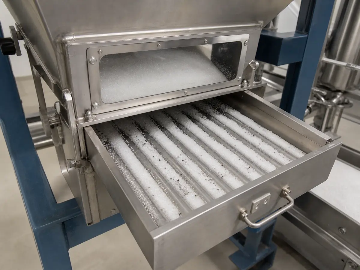
- The structure moves, cracks, distorts, or does not match the drawing.
- The magnet, cleaning belt, or captured iron can contact the conveyor or burden.
- Belt tracking cannot be stabilized within the equipment procedure.
- Iron falls back into material or enters an unsafe area.
- Actual peak burden, temperature, iron load, or environment exceeds the design input.
Installation Record
Keep equipment identification, drawing revision, installed height and datum, support approval, alignment, electrical checks, no-load result, loaded conditions, test result, photographs, training record, deviations, and final approval.
Pre-Commissioning Checks for a Suspended Magnet
| Decision rule | Verify support, orientation, working height, level, discharge path, guarding and maintenance access before testing capture. |
|---|---|
| Inputs to confirm | Approved drawing, magnet mass, lifting points, suspension hardware, belt width and speed, burden profile, target test pieces and safe access. |
| Risk or limitation | Do not energize drives or introduce material when temporary lifting gear, loose hardware or an obstructed discharge area remains in the attraction or moving zone. |
| Buyer action | Record four suspension dimensions, face-to-target gap, no-load checks and target capture at center and edges before handover. |
Safety Boundary Before Installation, Cleaning or Maintenance
- Before access, isolate and lock out the conveyor, separator drive and connected equipment under the site procedure; verify that movement cannot restart. A permanent magnet remains active after electrical isolation. Control suspended loads, pinch and nip points, attracted tools, loose steel, sharp collected iron and safe access around the belt and discharge zone.
- People with pacemakers or magnetically sensitive medical devices must follow medical-device and site restrictions; protect sensitive electronics and magnetic media.
- Our guidance is not a complete safe-work procedure. Approved manufacturer instructions, the site risk assessment, guarding and lifting plans, and lockout/tagout rules govern the work.
What We Need to Configure This Project
Input set for How to Install a Suspended Magnet Above a Conveyor
- How we use your data: We compare your material, contamination risk, production target and line interface before we configure a proposal or rule out an unsuitable option.
- Material: name and composition; dry or wet; powder, granule, lump, fibre or slurry; minimum, maximum and typical particle distribution; moisture, stickiness, tendency to cake or bridge, abrasiveness, corrosiveness, bulk density, normal temperature and maximum temperature.
- Production and target: normal and peak throughput, continuous or batch feed, feed uniformity, contaminant or recovery target, magnetic response if known, typical and maximum target size, initial concentration, acceptable residual and whether product loss is permitted.
- Installation: belt width and speed, normal and maximum burden depth, magnet position and rated working distance, available suspension and maintenance space, support and lifting arrangement; cleaning method, permitted shutdown, contact-material, wear and corrosion requirements; indoor, outdoor, washdown, high-humidity, dusty or hazardous-area conditions.
- Supporting project files: drive voltage, frequency and phase where a self-cleaning unit is considered; control interface and any site air requirement; destination country; current drawings, site photographs, running video and a representative material/contaminant sample when testing is needed.
- What you receive next: We use the confirmed inputs to prepare a project-specific drawing and inspection plan. We do not treat performance as confirmed until the agreed design and any required representative test or site acceptance establish the result.
Project Support
Need help selecting the right magnetic solution?
Send us your material, flow condition, target metal, capacity, installation space and any drawings or site photos. We will review the application and recommend the next practical step.
Frequently Asked Questions
Why is “Inline or Crossbelt Position” important for this decision?
Neither orientation is universally better. Compare real working distance, headroom, steel interference, iron path, maintenance access, and collection arrangement.
Why is “Set the Suspension Height Correctly” important for this decision?
Raising the magnet increases clearance but reduces attraction at the burden. Lowering it without approval may create collision, overload, or unsafe buildup risk.
Why is “Control Nearby Steel” important for this decision?
Ferrous idlers, beams, guards, chutes, tools, and platforms can distort the field, attract force, heat through movement in some conditions, or trap collected iron.