OSENC Magnetic Separation
Tube spacing must balance magnetic contact with material flow. Closer spacing can bring more powder near a magnetic surface, but reduces open area and increases bridging risk. Select from particle size, flowability, capacity, tube/sleeve diameter, row arrangement, and cleaning condition—not a standard gap copied from another material.
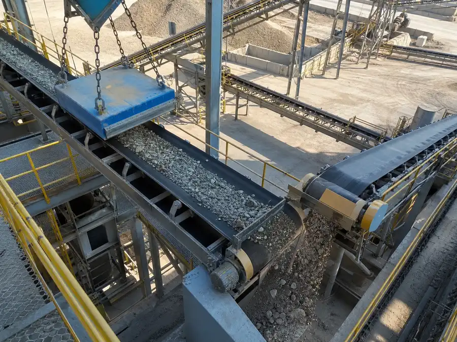
Inputs That Set the Spacing
- Maximum particle size and shape
- Free-flowing, cohesive, oily, damp, or static material
- Normal and surge flow
- Tube or easy-clean sleeve diameter
- Single, multiple, or staggered rows
- Deflectors and surrounding hopper geometry
- Acceptable pressure loss and cleaning interval
Why More Rows Are Not Always Better
Additional rows create more contact opportunities but add resistance and places for buildup. A staggered layout can redirect material, yet may also trap large or stringy pieces. Validate the full assembly with production-like feed.
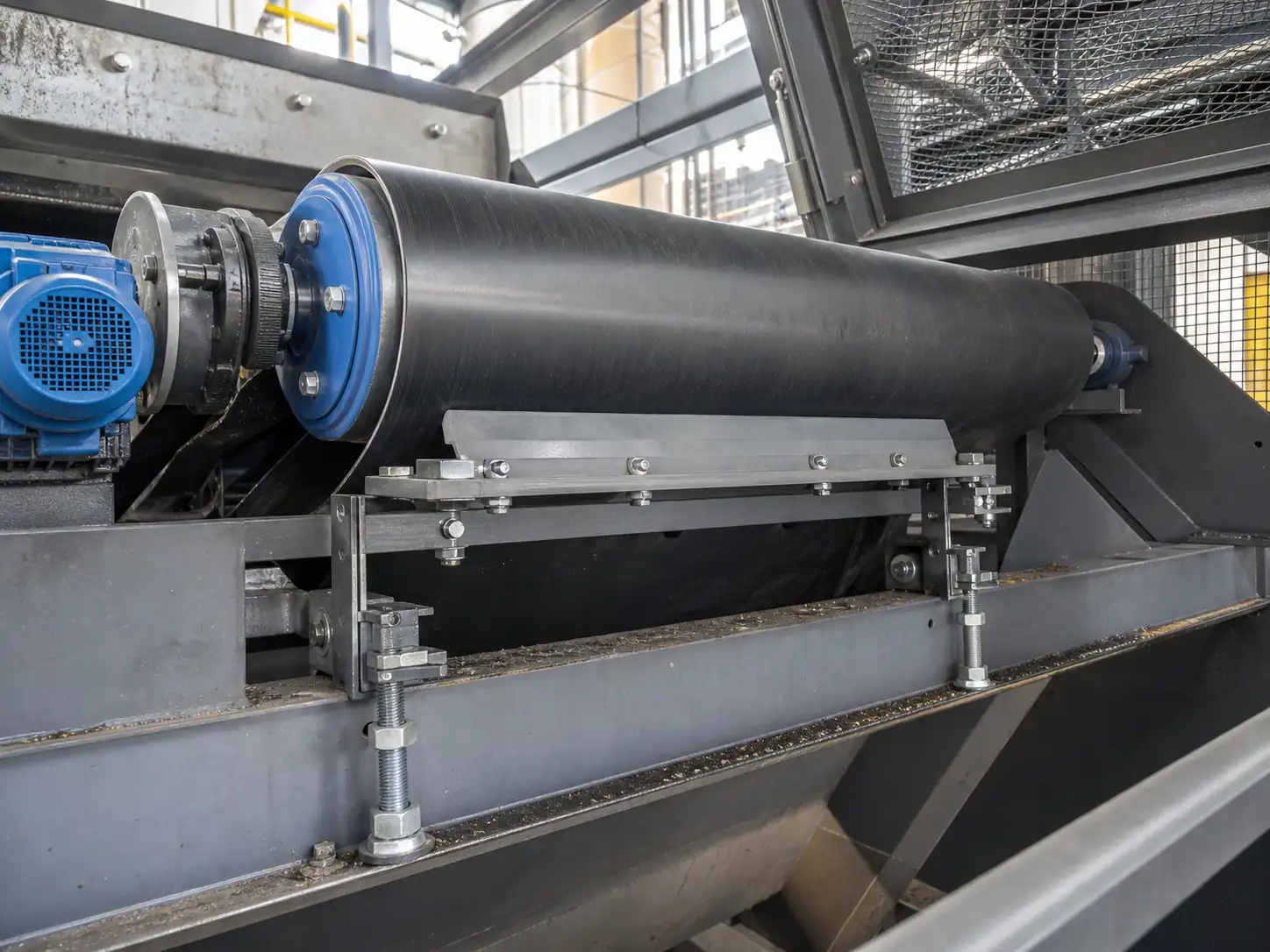
Easy-Clean Sleeves Change the Geometry
The outer sleeve may be larger than a standard tube and places material farther from the magnetic core. Recalculate open area and test magnetic performance at the assembled sleeve surface.
Practical Flow Test
Run representative material at normal and peak feed, observe bridging and bypass, record flow time and buildup, then inspect captured iron. Repeat after the expected cleaning interval. Do not claim capacity from opening area alone.
Common Spacing Errors
- Copying a gap from a different powder
- Ignoring the largest agglomerate
- Adding rows without recalculating open area
- Testing only the clean condition
- Using core diameter instead of sleeve diameter
Choose Tube Spacing from Flow and Coverage
| Decision rule | Closer spacing can reduce open area and increase contact opportunity, while wider spacing can improve flow but create uncovered paths; the correct compromise depends on material behavior and target size. |
|---|---|
| Inputs to confirm | Powder or granule size, bulk density, cohesion, moisture, product head, peak flow, target size, tube diameter, row count and cleaning interval. |
| Risk or limitation | Spacing selected only from a drawing can cause bridging, excessive restriction or bypass paths when the real material is cohesive or poorly distributed. |
| Buyer action | Use a representative flow test or documented operating evidence and inspect how material divides around the tubes before finalizing centers. |
Engineering Conditions Behind the Recommendation
- A high surface reading does not by itself predict capture in flowing product.
- Field gradient, shell or sleeve thickness, spacing, distance from each particle to a pole, particle size and magnetic response, flow speed, product depth, bridging and contamination buildup all change the result.
- Mechanical passage capacity is not the same as effective separation capacity.
- Quote or test conditions must identify material, size distribution, moisture, bulk density, normal and peak rate, feed distribution, speed, layer or flow geometry, contamination loading and cleaning interval.
How We Use This Technical Point in Selection
How to Select Magnetic Tube Spacing: seller-side application review
- Your selection risk: A device name, surface Gauss value or static pull result can lead to the wrong purchase when material motion and working distance are ignored.
- What we review: We check your material, particle size, moisture, temperature, throughput, layer or flow geometry, target contamination, installation position and cleaning method.
- What we decide: We use the principle described above to compare magnetic circuit, exposure, retention and discharge conditions before we recommend or rule out a structure.
- Buyer value: This helps you reduce leakage risk, avoid an oversized or ineffective unit and connect the specification to a testable production objective.
- Boundary: We do not treat a simplified explanation as guaranteed separation performance; representative testing is needed when magnetic response or scale-up remains uncertain.
- Next step: Send the material and target, particle range, moisture, temperature, throughput, contamination, installation drawing, available space, cleaning preference and any sample or site video. Send the material and separation target
Project Support
Need help selecting the right magnetic solution?
Send us your material, flow condition, target metal, capacity, installation space and any drawings or site photos. We will review the application and recommend the next practical step.
Frequently Asked Questions
Why More Rows Are Not Always Better?
Additional rows create more contact opportunities but add resistance and places for buildup. A staggered layout can redirect material, yet may also trap large or stringy pieces.
Why is “Easy-Clean Sleeves Change the Geometry” important for this decision?
The outer sleeve may be larger than a standard tube and places material farther from the magnetic core.
Why is “Practical Flow Test” important for this decision?
Run representative material at normal and peak feed, observe bridging and bypass, record flow time and buildup, then inspect captured iron.