OSENC Magnetic Separation
Choose the Material Path Around the Drum
Use the arrangement that presents a controlled, thin stream to the active magnetic zone and creates stable discharge paths for the real material. Top-feed arrangements introduce material above or onto the drum; bottom-feed arrangements carry or pass material beneath the drum region. Manufacturer terminology varies, so the approved cross-section and rotation direction matter more than the name.
Send Material and Layout Details Review Housed Magnetic Drums
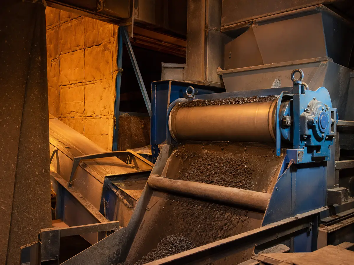
Do Not Compare Names Without Drawings
“Top feed,”“overfeed,”“underfeed,” and “bottom feed” may describe different paths among suppliers. Require a cross-sectional drawing showing inlet, material path, drum rotation, magnetic arc, nonmagnetic release, magnetic release, splitter, and both outlets.
General Comparison
| Question | Top/overfeed arrangement | Bottom/underfeed arrangement |
|---|---|---|
| How material reaches drum | Drops or is placed onto the upper region | Passes beneath or into a lower active region |
| Key control | Impact, spread, layer depth and bounce | Clearance, bed control, buildup and carry path |
| Wear concern | Impact on shell, liner, feed chute and splitter | Abrasion and trapped material at lower clearances |
| Maintenance concern | Access to inlet and upper shell | Access below drum and removal of accumulated material |
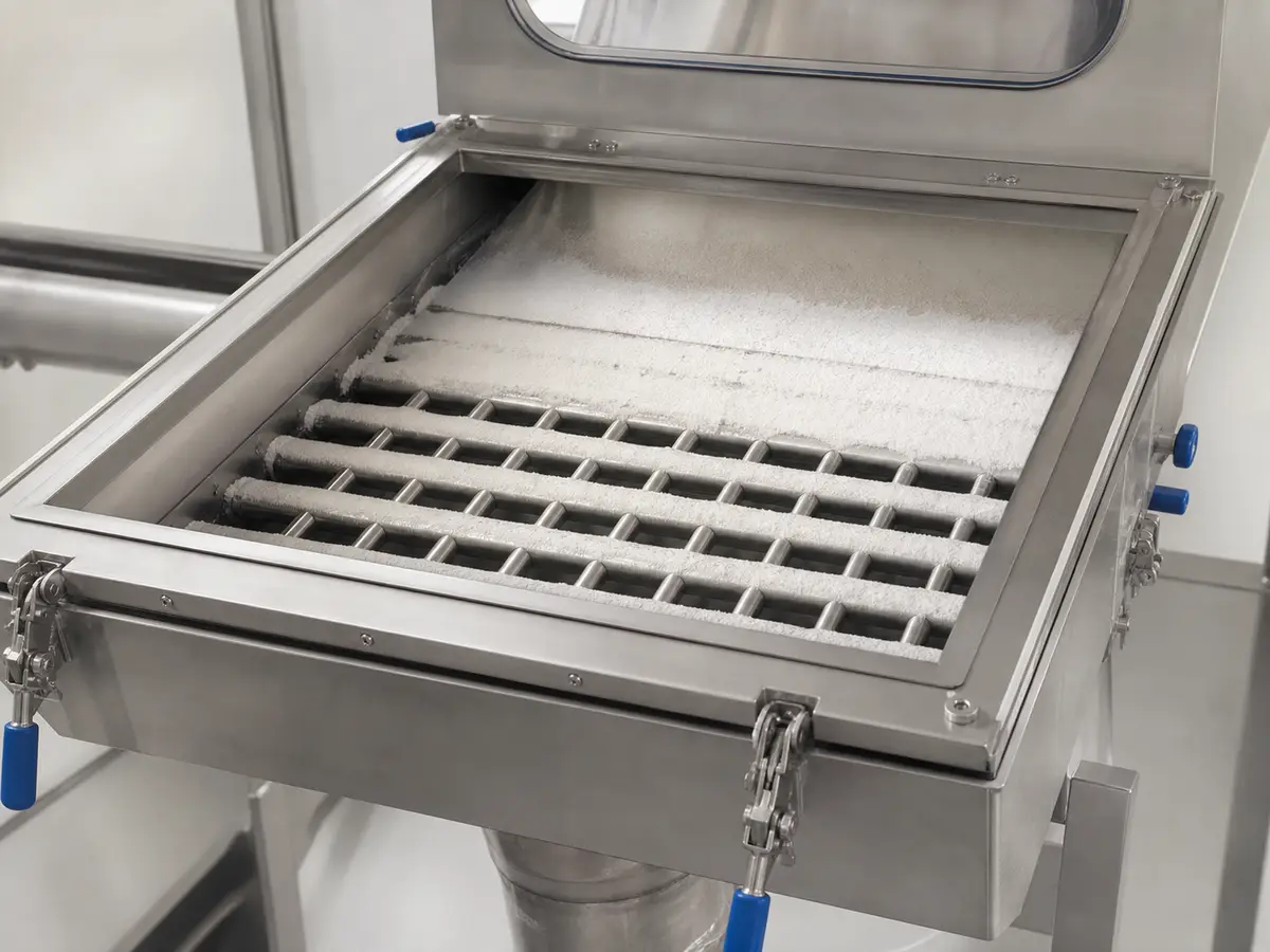
Top-Feed May Fit When
- Gravity feed and available headroom suit an inlet above the drum.
- A feeder or chute can distribute material across the working width.
- Impact, bounce, dust, and wear can be controlled.
- The required magnetic and nonmagnetic trajectories fit the outlets.
Bottom-Feed May Fit When
- The process layout naturally carries material beneath the active zone.
- Clearance and bed thickness can be maintained consistently.
- Sticky buildup, trapped oversize, and cleaning access are manageable.
- The drum can retain and release magnetic material into a separate path.
Variables That Can Reverse the Recommendation
Particle size, density, shape, moisture, stickiness, abrasion, magnetic response, liberation, feed rate, drum speed, magnetic arc, shell material, splitter location, and available space can all change the better arrangement. Test difficult or commercially critical material rather than copying another plant’s layout.

Capacity Needs Reference Conditions
Do not compare tonnes per hour without material, bulk density, size distribution, moisture, feed width, layer, drum dimensions, speed, and required product result. A feed arrangement that accepts more material but produces unstable trajectories may not deliver a better usable result.
Decision and Test Plan
- Define contamination and output acceptance.
- Draw both material paths within the available envelope.
- Review feeding, impact, wear, dust, cleaning, and maintenance.
- Test representative material at normal and peak conditions where practical.
- Sample both fractions and record product loss, carryover, and stability.
Select Feed Arrangement from Material Trajectory
| Decision rule | Top-feed and bottom-feed labels are secondary to how material contacts the shell, enters the magnetic arc and separates at the splitter. |
|---|---|
| Inputs to confirm | Particle and target size, feed velocity, layer depth, drum rotation and speed, magnetic arc, adhesion, bounce, dust and required outlet positions. |
| Risk or limitation | Changing feed side without rechecking rotation, arc and splitter can carry target into the wrong outlet or increase product loss. |
| Buyer action | Require a configuration drawing and representative test that records feed point, rotation, speed, splitter and both discharge fractions. |
What We Need to Configure This Project
Input set for Top-Feed vs Bottom-Feed Magnetic Drum: How the Feed Arrangement Changes Separation
- How we use your data: We compare your material, contamination risk, production target and line interface before we configure a proposal or rule out an unsuitable option.
- Material: name and composition; dry or wet; powder, granule, lump, fibre or slurry; minimum, maximum and typical particle distribution; moisture, stickiness, tendency to cake or bridge, abrasiveness, corrosiveness, bulk density, normal temperature and maximum temperature.
- Production and target: normal and peak throughput, continuous or batch feed, feed uniformity, contaminant or recovery target, magnetic response if known, typical and maximum target size, initial concentration, acceptable residual and whether product loss is permitted.
- Installation: feed chute and discharge geometry, drum or pulley diameter and working width, shaft/bearing interface, speed, splitter space, drive arrangement and maintenance access; cleaning method, permitted shutdown, contact-material, wear and corrosion requirements; indoor, outdoor, washdown, high-humidity, dusty or hazardous-area conditions.
- Supporting project files: drive voltage, frequency, phase and control interface; state whether any pneumatic actuator or air service is required; destination country; current drawings, site photographs, running video and a representative material/contaminant sample when testing is needed.
- What you receive next: We use the confirmed inputs to prepare a project-specific drawing and inspection plan. We do not treat performance as confirmed until the agreed design and any required representative test or site acceptance establish the result.
Project Support
Need help selecting the right magnetic solution?
Send us your material, flow condition, target metal, capacity, installation space and any drawings or site photos. We will review the application and recommend the next practical step.
Frequently Asked Questions
Do Not Compare Names Without Drawings?
“Top feed,”“overfeed,”“underfeed,” and “bottom feed” may describe different paths among suppliers. Require a cross-sectional drawing showing inlet, material path, drum rotation, magnetic arc, nonmagnetic release, magnetic release, splitter, and both outlets.
Why is “Variables That Can Reverse the Recommendation” important for this decision?
Particle size, density, shape, moisture, stickiness, abrasion, magnetic response, liberation, feed rate, drum speed, magnetic arc, shell material, splitter location, and available space can all change the better arrangement.
Why is “Capacity Needs Reference Conditions” important for this decision?
Do not compare tonnes per hour without material, bulk density, size distribution, moisture, feed width, layer, drum dimensions, speed, and required product result.