OSENC Magnetic Separation
Mechanical Interface and Separation Trajectory
A magnetic head pulley is not a drop-in replacement until shaft ends, bearings, pulley diameter and face, belt speed and wrap, drive arrangement, loads, lagging, rotation, magnetic arc, discharge trajectory, splitter, guards, and surrounding steel have been verified. Approve the replacement drawing before removing the original pulley.
Send the Existing Pulley Drawing Review Magnetic Head Pulley Selection
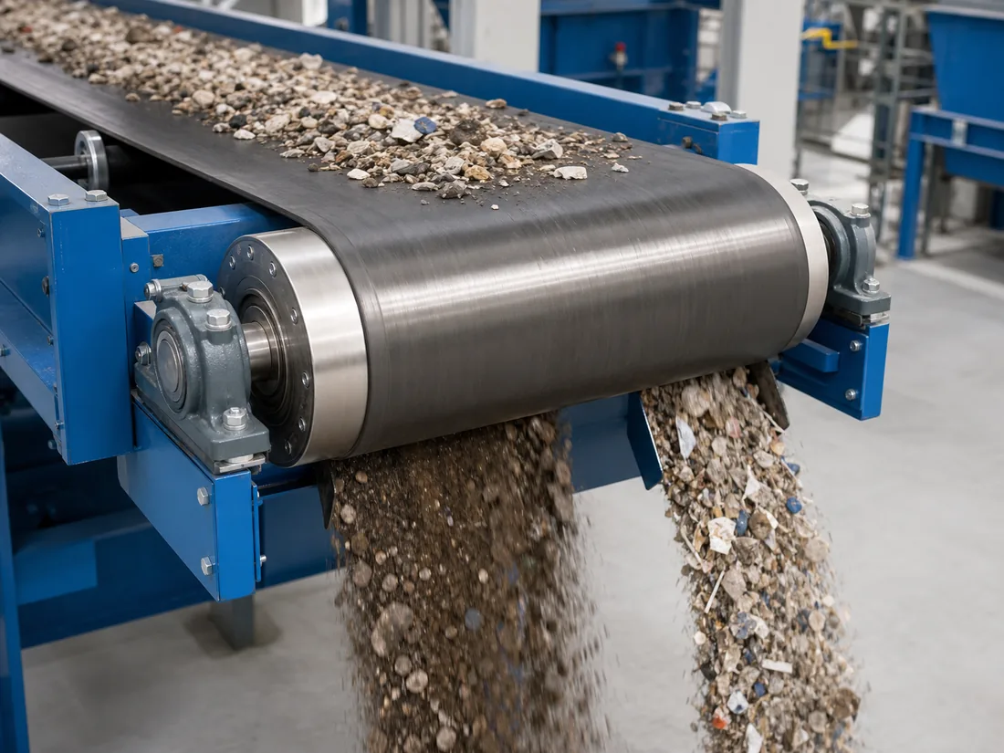
Capture the Existing Interface
- Pulley diameter, face width, shell/lagging, and crown if applicable
- Shaft diameter, steps, keyways, threads, shoulders, and overall length
- Bearing type, housing, centers, mounting height, and adjustment
- Drive coupling, sprocket, gearbox, torque path, and rotation
- Belt width, speed, tension, wrap angle, load, and splice
- Chute, scraper, guard, cleaner, and take-up interfaces
Verify Engineering Loads
The magnetic circuit adds mass and may change inertia, shaft stress, bearing load, startup demand, and support reactions. The responsible conveyor designer must verify the offered pulley for belt tensions, torque, bending, fatigue, speed, and duty. Do not approve a shaft from diameter alone.
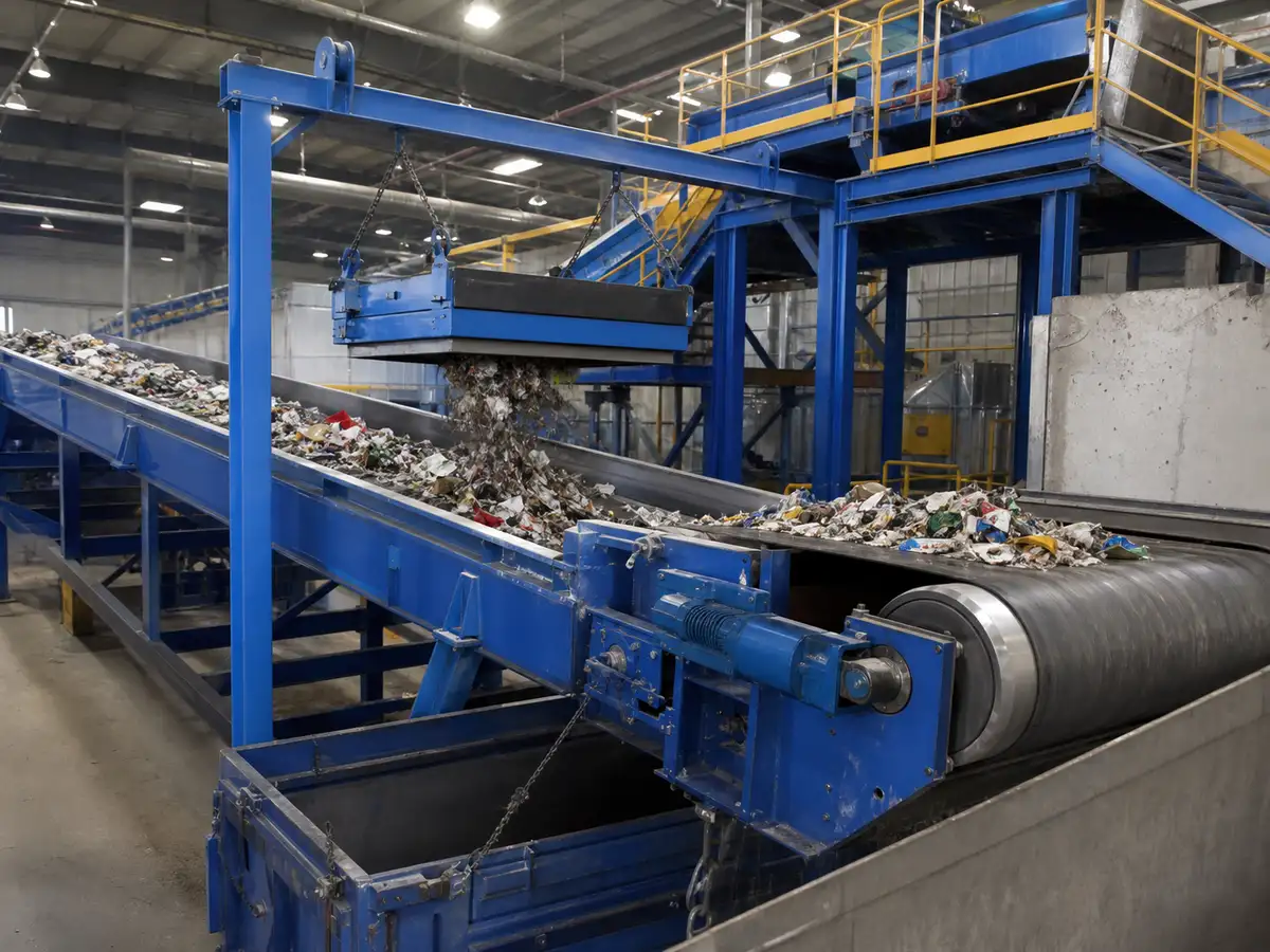
Confirm Magnetic Orientation Before Lifting
Identify rotation direction, active magnetic arc, nonmagnetic discharge zone, and shaft orientation on the drawing and the physical unit. Installing the pulley reversed may move the release point or reduce the intended separation trajectory. Protect the pulley from loose steel and control magnetic attraction during handling.
Installation Sequence
- Isolate the conveyor and follow the approved removal and lifting plan.
- Inspect supports, bearing seats, dimensions, and received pulley condition.
- Install bearings and pulley without forcing misaligned supports.
- Set shaft alignment, bearing position, and belt tracking by the conveyor procedure.
- Reconnect the drive and confirm guards, cleaners, chutes, and clearances.
- Rotate or jog under the approved procedure to verify direction and interference.
- Run empty, then load gradually while observing tracking, vibration, bearings, and trajectory.
Set the Splitter from Material Trajectories
Nonmagnetic material normally leaves the belt earlier, while responsive material follows the pulley farther before release. Place the splitter between the observed trajectories, allowing for particle-size, speed, feed depth, bounce, airflow, and attached nonmagnetic material. Never set it from a photograph of another conveyor.
Nearby Steel and Chute Design
Steel liners, chutes, cleaners, bolts, guards, and structural parts may attract captured iron or interfere with discharge. Review the magnetic clearance zone while preserving structural and guarding requirements. Use wear materials and geometry approved for the process.
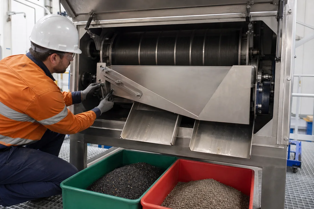
Commissioning Test
Record belt speed, feed rate, layer depth, material, target iron type and placement, splitter position, collected fractions, carryover, vibration, bearing observations, and adjustments. Test normal and peak conditions where safe. Do not equate the strongest surface reading with separation efficiency.
Stop and Investigate
- Bearing temperature, vibration, noise, or movement changes materially.
- The belt runs off center or contacts structures.
- The shaft, coupling, bearing housing, or support moves or loosens.
- Material plugs, rebounds, or crosses between discharge streams.
- Captured steel wraps around the pulley or cannot release safely.
Commissioning Checks Before Accepting the Pulley
| Decision rule | Confirm shaft and bearing alignment, belt tracking, rotation, wrap, guards and splitter clearance before evaluating magnetic separation. |
|---|---|
| Inputs to confirm | Approved pulley drawing, bearing centers, shaft fits, belt speed and tension, drive torque, lifting plan, target material and discharge trajectories. |
| Risk or limitation | Misalignment or a changed pulley diameter can create mechanical failure and alter the trajectory even when the magnetic circuit is correct. |
| Buyer action | Run no-load and loaded checks, record vibration and temperature, then sample both outlets after the splitter is adjusted. |
Safety Boundary Before Installation, Cleaning or Maintenance
- Before access, isolate and lock out the conveyor, separator drive and connected equipment under the site procedure; verify that movement cannot restart. A permanent magnet remains active after electrical isolation. Control suspended loads, pinch and nip points, attracted tools, loose steel, sharp collected iron and safe access around the belt and discharge zone.
- People with pacemakers or magnetically sensitive medical devices must follow medical-device and site restrictions; protect sensitive electronics and magnetic media.
- Our guidance is not a complete safe-work procedure. Approved manufacturer instructions, the site risk assessment, guarding and lifting plans, and lockout/tagout rules govern the work.
What We Need to Configure This Project
Input set for How to Install a Magnetic Head Pulley on a Conveyor
- How we use your data: We compare your material, contamination risk, production target and line interface before we configure a proposal or rule out an unsuitable option.
- Material: name and composition; dry or wet; powder, granule, lump, fibre or slurry; minimum, maximum and typical particle distribution; moisture, stickiness, tendency to cake or bridge, abrasiveness, corrosiveness, bulk density, normal temperature and maximum temperature.
- Production and target: normal and peak throughput, continuous or batch feed, feed uniformity, contaminant or recovery target, magnetic response if known, typical and maximum target size, initial concentration, acceptable residual and whether product loss is permitted.
- Installation: belt width and speed, normal and maximum burden depth, magnet position and rated working distance, available suspension and maintenance space, support and lifting arrangement; cleaning method, permitted shutdown, contact-material, wear and corrosion requirements; indoor, outdoor, washdown, high-humidity, dusty or hazardous-area conditions.
- Supporting project files: drive voltage, frequency and phase where a self-cleaning unit is considered; control interface and any site air requirement; destination country; current drawings, site photographs, running video and a representative material/contaminant sample when testing is needed.
- What you receive next: We use the confirmed inputs to prepare a project-specific drawing and inspection plan. We do not treat performance as confirmed until the agreed design and any required representative test or site acceptance establish the result.
Project Support
Need help selecting the right magnetic solution?
Send us your material, flow condition, target metal, capacity, installation space and any drawings or site photos. We will review the application and recommend the next practical step.
Frequently Asked Questions
Why is “Verify Engineering Loads” important for this decision?
The magnetic circuit adds mass and may change inertia, shaft stress, bearing load, startup demand, and support reactions.
Why is “Confirm Magnetic Orientation Before Lifting” important for this decision?
Identify rotation direction, active magnetic arc, nonmagnetic discharge zone, and shaft orientation on the drawing and the physical unit.
Why is “Set the Splitter from Material Trajectories” important for this decision?
Nonmagnetic material normally leaves the belt earlier, while responsive material follows the pulley farther before release.